How should a DIALux factory lighting calculation check dimmed operating scenes?
Check production, standby and cleaning lighting separately in DIALux, with the right task areas, control groups and output assumptions for each factory scene.
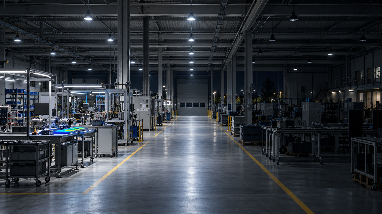
The short answer: calculate each scene for the work that remains active
A DIALux factory lighting calculation should check each proposed dimmed operating scene against the tasks, occupied areas and circulation routes that remain in use. A passing full-production calculation does not establish that a reduced-output scene is suitable. Define production, partial production, standby, cleaning and maintenance modes with the responsible project team, then calculate the actual luminaire-group settings for each required mode.
Keep the physical model and calculation basis coordinated while changing the agreed scene settings. DIALux supports scenes with different luminaire settings and dimming levels, but a calculated percentage does not establish the installed driver's behaviour or the factory's control logic. The report should identify what may operate in each scene and which results support that use.
1. Define the activity before choosing a dimming percentage
Start with an operating schedule rather than a desired energy-saving figure. Which machines run during the late shift? Are workers inspecting products, moving materials or only passing through? Does cleaning involve reading labels or seeing hazards beneath equipment? A standby scene suitable for an unoccupied bay may be unsuitable as soon as someone enters to troubleshoot a machine.
Ask operations, the electrical designer and the responsible consultant to agree the active tasks and applicable criteria for every mode. Record how occupancy changes the scene and what a worker must do before starting an activity that needs more light. This article supplies no universal reduced-output percentage or factory lux target: those decisions depend on the actual task and governing project requirements.
2. Map the model to control groups that can be installed
Group luminaires by the intended control arrangement, including task lights and circulation lighting where relevant. An assembly line, adjacent storage bay and main walkway may need separate commands. Check which luminaires overlap those areas before assigning a lower output: dimming the neighbouring bay can reduce useful light on the occupied line even when its own row remains at full output.
DIAL distinguishes luminaire groups used to define which fittings dim together in a scene from control groups generated for the calculation. The calculated grouping does not itself design circuits, addressing, sensors or control hardware. Use consistent group names in the DIALux file and the controls schedule, and have the electrical team confirm that each proposed combination can be reproduced.
3. Separate dimming from switching rows off
Uniformly reducing the output of all general lights and switching alternate rows off are different lighting tests. With selected rows off, overlap changes and local dark bands can appear between the remaining fittings. A similar total output or average illuminance does not make those arrangements equivalent. Calculate the actual intended pattern rather than applying an average reduction to the full-production result.
Retain the current machinery, partitions, conveyors, mounting coordinates, photometric files, maintenance assumptions and calculation surfaces across comparisons. Check the same occupied work surfaces and routes in every relevant mode. For a partially occupied factory, keep active task areas explicit; do not enlarge the averaging area to hide a weak workstation. Use consistent numerical and false-colour scales to compare the patterns.
4. Verify what the output setting represents
DIAL's light-scene guidance describes the default scene as using all luminaires at full luminous flux when unchanged. A dimmed scene therefore needs a documented light-output assumption for the selected product. Ask the supplier for the supported output range, the relation between a control command and output, any minimum setting, and whether the distribution remains appropriate at the intended setting. Changing the nominal product or optic requires a corresponding model update.
Do not label a luminous-flux percentage as the same percentage of electrical input without supporting data. DIAL's documented daylight-energy calculation uses specified system power and assumes a linear power-to-flux relationship for daylight-controlled luminaires. That is a modelling assumption; actual driver power, standby consumption and operating behaviour need product evidence. A lighting-scene result alone cannot establish annual energy savings.
5. Review the weakest active location in each mode
Check the agreed quantities for each occupied task area, surrounding area and route. These may include maintained average and minimum illuminance, the specified uniformity definition, vertical surfaces or glare where the brief requires them. Trace the controlling minimum to its location beside the machinery or between rows. A visually attractive rendering cannot replace those numerical checks.
For example, a cleaning mode may leave a surface behind a tall machine darker than the open floor even though the hall average appears adequate. A partial-production mode may affect the path between two active workstations. Test an appropriate group adjustment or local lighting change and recalculate affected modes. Emergency lighting requires its own agreed design and evaluation; a reduced general-lighting scene does not establish emergency performance.
6. Give the report a scene-to-operation schedule
For each scene, list the permitted activities, occupied zones, active luminaire groups, output assumptions, calculation surfaces, criteria and controlling results. Include the group plan and a table of scene settings. Identify the drawing revision, product variants, photometric files, maintenance basis and software version so a reviewer can understand which installation the results describe.
State the unresolved items: provisional machinery positions, unconfirmed driver data, daylight assumptions, control overrides, occupancy transitions and commissioning settings. Calculations can support project evaluation, procurement or submission; acceptance remains with the relevant client, consultant or authority. On-site control programming and measured verification are separate work that the report should assign clearly.
A practical decision checklist for factory scenes
Before calculation, confirm: (1) current machine and work-zone drawings; (2) the activities and occupied routes in each mode; (3) applicable task criteria; (4) exact luminaires and photometry; (5) feasible groups and supported output behaviour; and (6) whether daylight and energy assessment are in scope.
Before issue, verify: (1) every retained scene has current results; (2) group names match the controls schedule; (3) reduced modes preserve required active-area performance; (4) minima and uniformity are traceable; (5) light-output assumptions are distinct from electrical consumption claims; and (6) entry, override, commissioning and acceptance responsibilities are recorded. If an active task fails, change the lighting or restrict that scene's use rather than describing the full-output result as proof.
How LUXGRID can help define the calculation scope
Send the current plan, machinery layout, luminaire files and an operating schedule showing which zones remain active. A useful enquiry names the scenes to assess and the outputs required, instead of asking only whether dimming is possible. LUXGRID can discuss a calculation package that tests those operating conditions and documents its assumptions and limits.
The official DIAL references below substantiate scene settings, grouping and the stated energy-model assumption. The factory examples and decision checks in this guide are practical engineering considerations, not a claim that software settings alone prove a safe installation or provide an approval.
Official technical references
- DIAL: indoor lighting and lighting scenes
- DIAL knowledge base: light scenes
- DIAL knowledge base: luminaire and control groups
- DIAL: scene documentation and energy calculation assumptions
For physical work-zone modelling, read our factory machinery and task-zone guide.
Frequently asked questions
Can I estimate a dimmed factory scene by multiplying the full-output average lux?
That may offer a rough sensitivity check only under clearly supported assumptions. It does not replace scene results for each active task, particularly when different groups dim or switch off. Calculate and review the intended operating pattern and its controlling locations.
Does a 50% DIALux light-output setting prove a 50% electricity saving?
No. The output setting and electrical input are different quantities. Use verified driver and luminaire power data, the relevant model assumptions, control behaviour and operating hours for an energy estimate.