Can one DIALux sports-lighting model compare training and match scenes?
Use one coordinated DIALux sports-lighting model to compare training and match scenes without hiding changes in aiming, dimming, evaluation areas or glare checks.
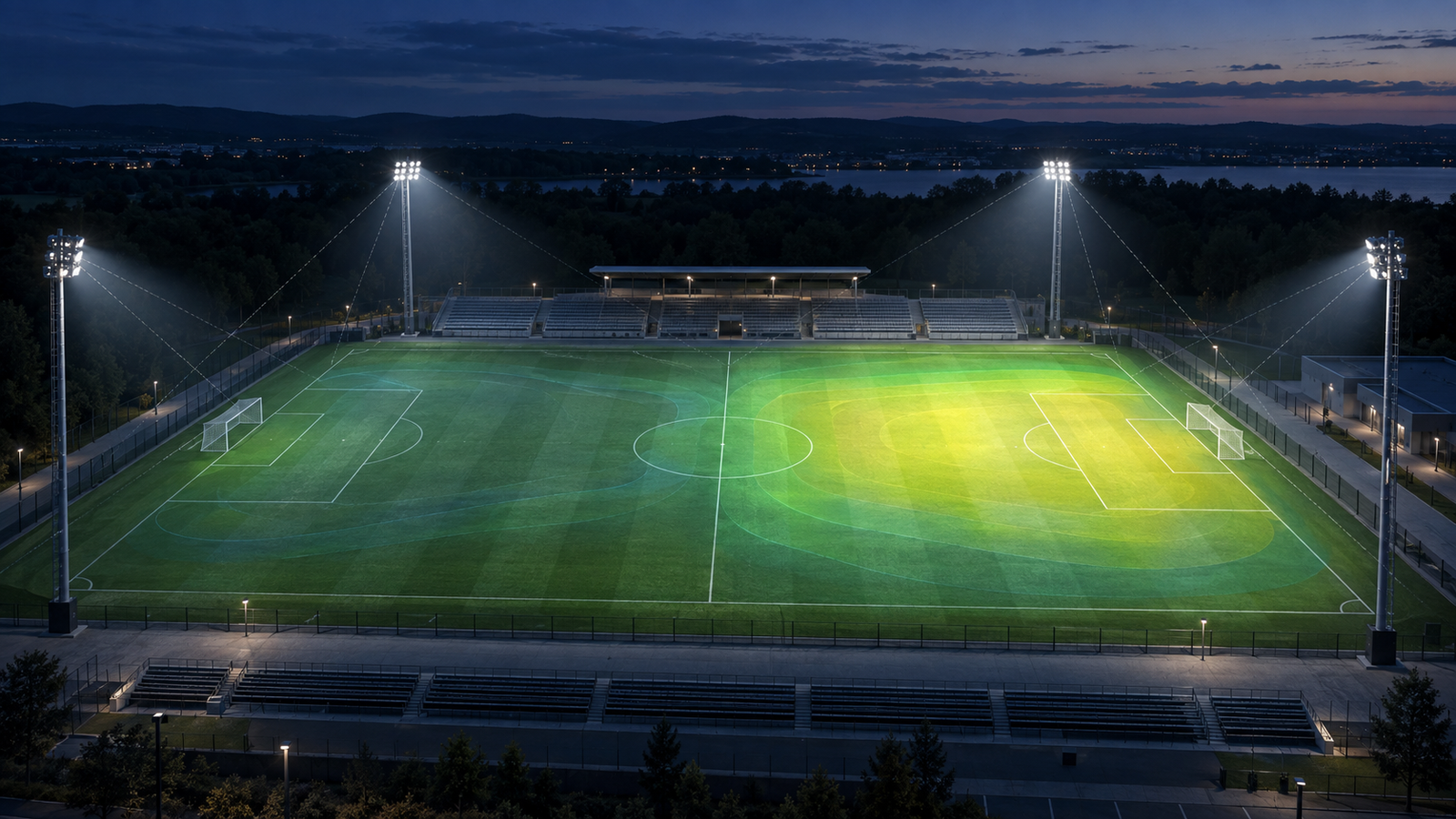
The short answer: keep one coordinated geometry, then calculate each operating scene
One DIALux sports-lighting model can compare training and match scenes when the field geometry, poles, floodlight positions, aiming and verified photometry remain coordinated. Create clearly named luminaire groups and scenes for the actual operating modes, assign the intended switching or dimming state, and calculate every scene against the evaluation areas and criteria that genuinely apply to that use.
Do not treat a training scene as a darker rendering of the match scene. It is a separate operating condition that needs its own active luminaires, control levels, result tables, uniformity review, glare or spill checks where required, and documented limitations. The calculation can support design evaluation, procurement or a submission, but the client, consultant and relevant authority or sports body must confirm the applicable requirements and acceptance method.
1. Freeze the shared physical model before comparing controls
Start with the latest field plan, playing-area dimensions, line markings, pole coordinates, mounting heights, structural limits and surrounding receptors. Use the exact proposed floodlight variants and photometric files, and record every aiming direction with a repeatable convention. If one scene silently uses different geometry or aiming, the comparison no longer isolates the control strategy.
A single coordinated model also makes revisions traceable. When a pole, floodlight, optic or aiming point changes, update the common installation first and recalculate every affected scene. Do not preserve an old training result beside a newer match arrangement simply because both reports came from the same project file.
2. Define scenes from real use, not convenient percentages
Describe what each mode is for: maintenance, community practice, team training, a match, broadcast operation or another agreed event. Map floodlights to control groups that can exist in the electrical and control design. Then use switching or dimming levels supported by the selected drivers and manufacturer data rather than inventing a percentage solely to reach a target result.
A training scene may use fewer floodlights, reduced output or both. Those choices can change overlap, uniformity, glare, colour appearance and the location of dark zones. A nominal fifty-percent power scene does not necessarily produce half of every illuminance value, especially when groups switch off and the spatial distribution changes.
3. Keep the evaluation areas comparable and the criteria explicit
Use the same coordinated playing surface and grid where the purpose is to compare coverage patterns. Confirm whether each operating mode has a different target or class, and state that difference beside the result instead of moving the grid or changing its resolution to improve a scene. Include goal areas, touchlines, technical zones or vertical planes only when the brief requires them.
Review maintained illuminance, minimum values and the applicable form of uniformity for each named area. Where the project requires vertical illuminance, glare, spill light, spectator areas or camera directions, calculate those quantities in the relevant scenes as well. A training scene that passes one horizontal average should not be presented as equivalent to a match scene with broader visual and operational requirements.
4. Diagnose what changes when groups switch or dim
Compare numerical tables, isolines, value charts and false-colour views using consistent scales. Look for new minima between active floodlights, weakened goal-mouth coverage, abrupt gradients, dark technical zones and changed glare directions. When one group is dimmed, verify that the scene assignment and output level are shown correctly in the report.
Do not repair a weak training scene by altering only the colour legend or by judging the photorealistic view. Test a control regrouping, a supported dimming level, revised aiming or a different optic, then recalculate every affected quantity. Check that the solution does not create worse match-mode glare or spill beyond the field.
5. Separate calculation scenes from the final controls specification
DIALux can model luminaire groups, lighting scenes and dimming levels, but the model is not the completed control system. The electrical designer and supplier still need compatible drivers, circuits, addressing, control logic, fail states and commissioning settings. Record how each calculated group maps to the proposed installation so the scene can be reproduced on site.
Allow for tolerances, lumen maintenance, aiming accuracy, voltage and thermal effects, and any product-specific dimming limits. A result calculated at a precise software percentage should not be described as guaranteed field performance without verified product behaviour and commissioning measurements.
6. Issue a scene schedule that another reviewer can audit
For every scene, list its purpose, active groups, switching or dimming state, assumed output, calculation areas, criteria and controlling results. Include the shared luminaire schedule, pole and aiming plan, relevant result pages and a short explanation of why the retained scene is operationally useful. Use consistent names in the model, drawings, controls schedule and report.
State what the study does not prove. It cannot confirm the installed control programming, final aiming, field cleanliness, electrical capacity, actual maintenance or authority acceptance. Those items need coordination and, where required, commissioning and measurement after installation.
Training-versus-match decision checklist
Before calculation, confirm: (1) the latest field and pole geometry; (2) the exact floodlights, optics and photometric files; (3) repeatable aiming records; (4) real control groups and supported dimming behaviour; (5) the use and criteria for every scene; and (6) surrounding receptors, operating times and other project constraints.
Before issue, verify: (1) all scenes use the current shared installation; (2) active groups and levels are documented; (3) evaluation areas and grids remain comparable; (4) average, minimum, uniformity, glare, vertical and spill results are checked where applicable; (5) visual scales are consistent; and (6) control, commissioning and approval responsibilities are explicit.
Authoritative sources used for this guide
DIAL's current outdoor-lighting guidance says DIALux evo can create lighting scenes with different dimming levels, compare scenarios inside one project and document which luminaires belong to each scene. Its official training material also describes creating and duplicating scenes, grouping luminaires, defining dimming values, calculating scenes and documenting control-group data.
DIAL's current product information lists CIE 112 for outdoor and sports glare and EN 12464-2 among supported outdoor references, while also noting broader outdoor calculation and documentation tools. Use the licensed standard, applicable national or sports-body requirements and the project brief to set acceptance criteria; software support does not determine which rule governs a particular facility.
Frequently asked questions
Can I model a training scene by reducing every floodlight to the same percentage?
Only when that control strategy is physically supported and matches the intended operation. Many training modes use selected groups, dimming or both, so calculate the real grouping and verify its coverage, uniformity and other required results.
Does a passing match scene mean the training scene also passes?
No. Switching or dimming changes overlap and can move the darkest points, alter uniformity and affect glare or spill. Calculate and document each operating scene against the criteria that apply to its use.