How should a DIALux sports-lighting calculation check spill light beyond the field?
Plan a DIALux sports-lighting spill-light check around boundaries, nearby windows and viewing directions without relying on the field average alone.
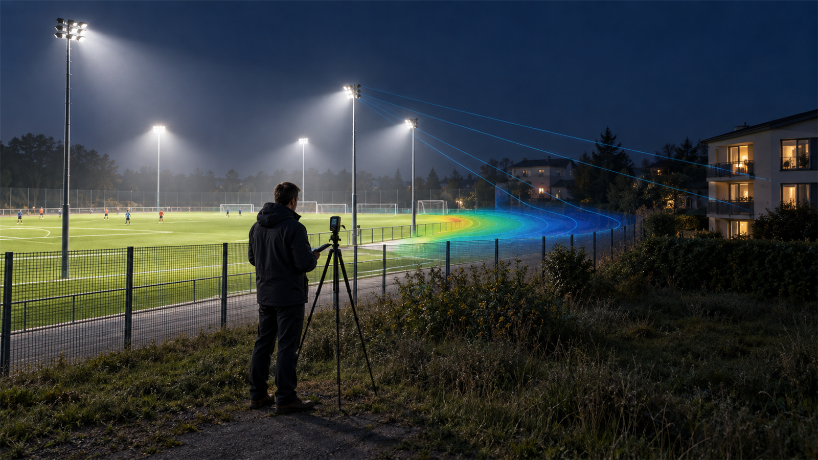
The short answer: model the receptors outside the field as deliberately as the playing area
A DIALux sports-lighting calculation should not stop after the pitch reaches its target average, minimum or uniformity. Build the actual site boundary and relevant surroundings, identify the locations and viewing directions that can receive unwanted light, create the applicable operating and curfew scenes, and calculate the specific obtrusive-light quantities required by the project criteria. Then adjust optics, aiming, mounting and shielding while rechecking the field itself.
Spill light is light falling outside the area intended to be lit. Obtrusive light is the part whose amount or direction causes an unwanted effect, so the boundary line alone is not always the decisive receptor. A nearby bedroom window, road user, neighbouring property, ecological area or skyward component may need a different calculation object and metric.
1. Fix the boundary, receptors and acceptance basis before aiming luminaires
Start from a coordinated site plan with the field, fence, property boundary, nearby buildings, window heights, roads, level changes, trees or permanent screens, mast positions and intended mounting heights. Confirm which neighbouring locations are sensitive, which viewing directions matter and whether assessment changes before and after a stated curfew. An approximate empty rectangle cannot represent a residential facade beyond a slope or a road seen from a particular approach.
Record the governing client, consultant, planning or authority criteria and their environmental zone or equivalent context. Do not insert a familiar limit from another country or project. CIE 150:2017 provides guidance for limiting obtrusive effects and DIALux supports several standards and guidelines, but the project team must establish which basis, timeframe and limit values actually apply.
2. Use the exact photometry, orientation and physical context
Import current IES or LDT data for the exact floodlight, optic, lumen package and tilt arrangement. Place each luminaire at its real XYZ coordinate and rotation, not merely at the correct mast. Small aiming or tilt changes can move high-intensity parts of the distribution beyond the touchline. Check whether the photometric file represents accessories such as louvers, visors or shields that the design assumes.
Model buildings, terrain and major permanent barriers where they materially block, reflect or redirect light. Assign supportable surface properties and keep temporary vegetation assumptions separate from permanent mitigation. A screen that appears effective in plan may leave an elevated window exposed, while an overly simplified solid object may create false protection.
3. Build operating scenes that match how the venue will be used
Separate full competition, training, cleaning, security and curfew states when their luminaire groups or outputs differ. Include only the fittings expected to operate in each scene and document the control logic. If the applicable assessment requires a post-curfew condition, calculate that condition rather than assuming the full-output result can be scaled without regard to which luminaires switch or dim.
DIAL's official documentation for evo 13 introduced a dedicated obtrusive-light scene with a maintenance factor of 1 by default and a checklist for required settings. Use the software's current verified workflow for the project version, and keep the ordinary maintained sports-performance scene separate so reviewers understand why the calculation bases differ.
4. Place calculation objects at the people and places that receive the light
Use vertical calculation surfaces or points at relevant facades, windows and boundary locations, with heights and orientations that match the agreed receptor. Add observer-related objects for glare or luminous-intensity assessment only where the governing method requires them, and use suitable skyward or site-wide measures when upward light is part of the brief. A single horizontal grid outside the fence cannot answer every obtrusive-light question.
DIALux evo's documented obtrusive-light tools can evaluate quantities including vertical illuminance, luminous intensity, glare-related values and upward-light ratios, depending on the object and selected method. Some values require additional inputs. Configure only the metrics that the chosen standard or brief supports, label non-standard diagnostic checks clearly, and preserve each object's position, orientation and evaluation timeframe in the report.
5. Find the source of each maximum, not only the coloured contour
Review maximum values at every receptor and trace which floodlight or group contributes. DIAL's current guidance notes that obtrusive-light results are assessed as maximum values rather than lighting targets and that contributing luminaires can be identified in the CAD view. That makes the result actionable: the designer can test an optic, tilt, aim point, output level, mounting location or shield instead of lowering all field light indiscriminately.
False colours and isolines are useful for explaining patterns but do not replace numerical checks. Keep the scale fixed when comparing options and inspect isolated hot spots at windows, corners and elevation changes. A visually smooth spill contour can still conceal one critical viewing direction or a narrow high-intensity lobe.
6. Optimise spill and playing performance together
For each mitigation option, recalculate the field average, minimum, uniformity, vertical illuminance, glare and any broadcast or spectator criteria in scope. A tighter optic or lower tilt may reduce a boundary value while creating dark zones, harsh gradients or excessive intensity elsewhere. A higher mast may improve aiming geometry but changes structure, cost, planning appearance and access.
Compare options on an unchanged model and receptor set. Useful variables include asymmetric or narrower optics, revised cross-aiming, lower output, different mast locations, luminaire grouping, physical shielding and curfew scenes. Document why the selected arrangement balances the playing task with the verified external limits; do not claim that one product or one aiming rule is universally compliant.
7. Issue an auditable spill-light report
The report should identify the site plan and coordinate origin, field and boundary geometry, receptor positions and orientations, nearby obstructions, exact photometric files, mast heights, aiming coordinates, luminaire groups, operating scenes, environmental zone or project classification, curfew basis, calculation quantities and pass/fail source. Include maximum-result pages and enough plan or elevation views for another reviewer to locate the controlling point.
State limitations such as unverified window use, uncertain terrain, future vegetation, missing architectural screening, installation tolerances and whether field aiming will be commissioned on site. A DIALux calculation can support project evaluation or submission, but it does not itself grant planning permission or authority acceptance. Final acceptance rests with the relevant client, consultant or authority.
Sports-field spill-light decision checklist
Before modelling, confirm: (1) surveyed field, boundary, mast and receptor coordinates; (2) window and observer heights and orientations; (3) terrain, buildings and permanent screening; (4) exact IES or LDT files, optics, accessories and output; (5) operating and curfew scenes; and (6) the governing criteria, environmental classification and timeframes.
Before issue, verify: (1) every required receptor and quantity has been calculated; (2) maximum values and contributing luminaires have been reviewed; (3) false-colour scales are consistent across options; (4) field performance still works after mitigation; (5) assumptions, exclusions and installation tolerances are stated; and (6) the report identifies who must accept the result.
Authoritative references used for this guide
CIE 150:2017, Guide on the Limitation of the Effects of Obtrusive Light from Outdoor Lighting Installations, explains the purpose of assessing environmental effects and gives recommended limits for relevant parameters. The CIE's 2025 position statement distinguishes obtrusive light from the broader concept of light pollution and reinforces the need to avoid disproportionate unwanted effects from lighting at night.
DIAL's official DIALux evo 13 and 13.1 documentation describes the dedicated obtrusive-light scene, configurable calculation objects, environmental-zone and timeframe selection, maximum-value review, contributing-luminaire indicators and report output. DIAL's current download page lists DIALux evo 14 as the available major version; confirm the exact controls and project compatibility in the version used for the calculation.
Frequently asked questions
Is checking horizontal lux at the sports-field boundary enough?
Usually not. The applicable brief may require vertical illuminance at facades or windows, luminous intensity or glare from particular viewing directions, and upward-light measures. Establish the governing criteria first and place calculation objects at the actual receptors.
Can reducing floodlight tilt always solve spill light?
No. Aiming changes can reduce one external maximum but worsen field uniformity, vertical illuminance or another receptor. Test optics, output, position, shielding and operating scenes together, then recalculate the field and every agreed spill-light object.