How should a DIALux street-lighting calculation check pedestrian crossings?
Model the crossing, approaches and pedestrian visibility separately so a DIALux road result does not hide weak vertical illumination or contrast.
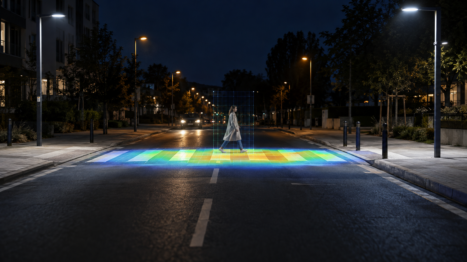
The short answer: calculate the road and the person a driver must see
A DIALux pedestrian-crossing lighting calculation should not stop at the average or uniformity on the painted road surface. Build the actual road profile and crossing approaches, apply the authority's agreed road or conflict-area criteria, then add the horizontal and vertical calculation objects needed to examine a pedestrian from each relevant driver approach. Review contrast, glare, obstructions and the transition into the surrounding street before deciding that the crossing is adequately visible.
DIALux evo can create configurable street profiles, assign lighting classes and report evaluation fields. Its outdoor workflow also supports calculation surfaces and points, isolines, value charts and false colours. Those tools support a project decision, but they do not select the applicable national rule or prove that every pedestrian is visible in every real condition. Acceptance remains with the responsible client, road authority and consultant.
1. Start with the crossing layout and every driver approach
Request a coordinated plan showing carriageway width, lane directions, crossing type, stop or give-way positions, kerbs, refuge islands, footways, cycle tracks, nearby junctions, parking, bus stops, trees, signs, signal equipment and existing columns. Confirm which approaches and turning movements must see a person at the waiting area and across each part of the crossing. A central island may divide the movement into separate stages even when it looks like one stripe in plan.
Do not model a generic straight road when the real crossing sits beside a bend, crest, junction or offset approach. Sight direction changes which face of a pedestrian matters and which background the driver sees. Record the design speed, traffic direction and left- or right-hand traffic convention without inventing a universal observation distance; the responsible road authority must provide or approve the assessment basis.
2. Choose the road and conflict-area criteria before modelling
CIE 115:2010 distinguishes lighting classes for motorised traffic, conflict areas and pedestrian areas through M, C and P concepts. DIAL's current street-lighting documentation says DIALux evo creates evaluation fields, assigns a lighting class and allows the modeller to adjust it, while national requirements can vary. Confirm whether the crossing belongs inside an existing conflict area or requires a separate crossing assessment under the applicable local guidance.
Avoid copying a target from another country or a different crossing type. The relevant authority may require supplementary horizontal or vertical checks, a contrast strategy, a defined approach zone or particular equipment. Record the edition and national adoption used by the project. The calculation should show how the selected criteria were applied, not present software defaults as the authority's decision.
3. Keep road-surface results and pedestrian visibility as separate questions
The standard road calculation can show results for the carriageway and configured road elements, but a bright crossing surface does not automatically make a pedestrian conspicuous. A person can be seen in positive or negative contrast depending on the lighting direction, clothing, background luminance and driver viewpoint. That is why a credible review needs both the surface result and a deliberate assessment of the vertical plane occupied by the pedestrian.
Create clearly named vertical calculation surfaces at representative positions across the waiting area, kerb, first traffic lane, centre or refuge island and far side when the project brief calls for them. Orient each plane towards the relevant approach and use a documented height and extent. If the adopted method requires multiple faces or grids, calculate them separately rather than rotating one favourable plane to serve every direction.
4. Model approaches, islands and adjacent pedestrian space
Extend the calculation far enough to examine the lighting transition before and after the crossing. Include footway waiting areas and refuge islands where people pause, and check the kerb line, tactile area or ramp when its geometry affects the calculation. The objective is not to create a decorative bright rectangle but to understand how the pedestrian enters, occupies and leaves the driver's field of view.
Use the exact road surface and street profile for the carriageway calculation. DIALux evo allows detailed street elements such as lanes, sidewalks, bike paths, parking strips, green strips and medians. Verify that the modelled widths, offsets and materials match the approved plan; moving a crossing or island by one imported drawing revision can change both column geometry and the relevant sight line.
5. Use verified photometry and check glare from the approach
Obtain the exact IES or LDT file, lumen package, optic, mounting height, outreach, tilt, rotation and control state for every proposed luminaire. Supplementary crossing optics are often directional, so a mirrored or reversed installation can illuminate the wrong side of the pedestrian. Check the orientation in plan and 3D, then confirm that the report identifies it clearly enough for installation review.
Review glare and bright sources from each approach as well as the numerical values on the crossing. More light is not automatically better if a luminaire masks the pedestrian, produces a distracting hotspot or creates a harsh transition from the adjacent road. Test position, distribution, aiming and mounting before simply increasing output, and include any dimmed or time-dependent scene that the project genuinely intends to operate.
6. Test credible obstructions and backgrounds
Trees, parked vehicles, bus shelters, signal heads, signs and street furniture can block light or change the background behind a pedestrian. Model permanent geometry accurately and agree which variable obstructions need a separate scenario. Do not place a parked vehicle over every possible space, but do not issue a clear crossing view if legal parking or a shelter can predictably hide the waiting area.
Use a consistent false-colour scale and calculation settings when comparing the base and obstructed cases. Inspect the minimum locations on horizontal and vertical surfaces, not only averages. CIE 236:2019 summarises empirical evidence on how lighting affects pedestrian visual impressions and performance; it reinforces why a crossing review should consider the human visual task rather than only a road-surface number.
7. Issue a report that another reviewer can audit
The report should identify the drawing revision, crossing type, road geometry, traffic directions, observation approaches, applicable criteria, exact luminaires and photometry, mounting and orientation, surface properties, maintenance basis, horizontal and vertical calculation objects, grid settings, lighting scenes, results and controlling minima. Include plan and 3D views that show which vertical plane faces which approach.
State limitations such as unverified sight distances, provisional landscaping, uncertain parking controls, vehicle headlamps not modelled, wet-road behaviour, installation tolerances or criteria awaiting authority confirmation. A DIALux street-lighting calculation can support design evaluation, coordination or a submission package, but it does not certify road safety or grant approval.
Pedestrian-crossing calculation checklist
Before modelling, confirm: (1) the approved crossing and road layout; (2) every vehicle and turning approach; (3) the road, conflict-area and crossing criteria; (4) exact luminaires, photometry and orientation; (5) waiting areas, islands, footways and cycle tracks; and (6) credible permanent or variable obstructions.
Before issue, verify: (1) road evaluation fields match the geometry and class; (2) vertical planes face the correct approaches; (3) minima, uniformity, contrast context and glare have been reviewed; (4) base and obstruction scenarios use consistent settings; (5) report views identify every calculation object; and (6) assumptions, limitations and acceptance responsibility are explicit.
Authoritative references used for this guide
DIAL's official street-lighting guidance describes configurable road profiles, adjustable lighting classes, automatic evaluation fields, luminaire arrangements, optimisation and documented result grids. Its outdoor-lighting guidance describes calculation surfaces and points, results monitoring, isolines, value charts, false colours, 3D objects and lighting scenes.
CIE 115:2010 covers lighting classes for motorised traffic, conflict areas and pedestrian areas. CIE 236:2019 summarises empirical evidence on lighting for roads where pedestrians are the primary users. Use the licensed standards, current national requirements and the project authority's brief to set criteria; this article does not reproduce or replace them.
Frequently asked questions
Is horizontal illuminance on the crossing enough for a DIALux assessment?
Not by itself. The road or conflict-area result may be required, but pedestrian visibility can also depend on vertical illumination, contrast, glare, background and the viewing direction from each approach. Use the calculation objects and criteria agreed for the project.
Should one vertical calculation plane face both traffic directions?
Usually the orientations should be checked separately when drivers approach from different directions. A plane facing one approach can give a favourable result that does not describe the opposite face of the pedestrian. Follow the authority's agreed method and document every plane.