How should a DIALux industrial-yard calculation model cranes and stacked materials?
Model cranes, material stacks and changing work zones in a DIALux industrial-yard lighting calculation without hiding shadow risks behind one empty-yard result.
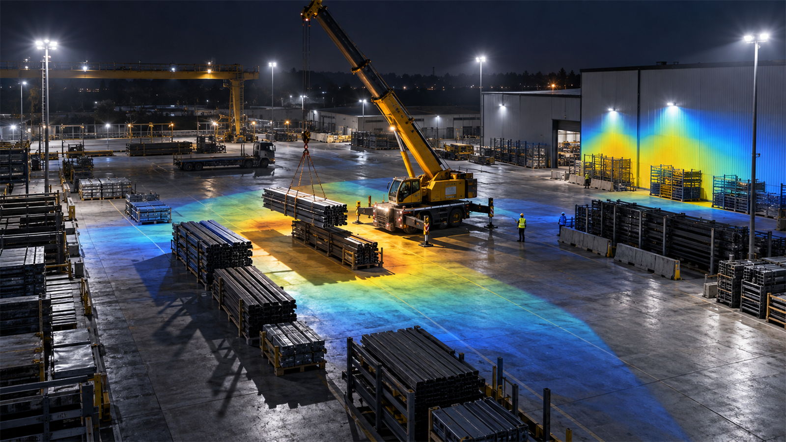
The short answer: calculate representative operating scenarios, not one permanently empty yard
A DIALux industrial-yard lighting calculation should model the permanent site accurately, then test representative crane positions, material-stack arrangements and active work zones that can block light or change the visual task. Keep the same verified luminaires and acceptance basis across each scenario, place calculation objects on the relevant horizontal and vertical task surfaces, and compare minima, uniformity, glare and shadow locations rather than relying on one average for an unobstructed yard.
The objective is not to predict every future load position. It is to show whether the proposed lighting remains usable across credible operating states and to identify conditions that require controls, local task lighting or operational restrictions. The customer, consultant and relevant authority must agree which scenarios and criteria are representative.
1. Separate fixed geometry from changing operational obstructions
Start with a coordinated survey or site plan showing buildings, canopies, fixed gantries, columns, fences, terrain, work lanes, crane travel limits, stock zones and luminaire coordinates. Model permanent objects whenever they materially block, reflect or receive light. Confirm mounting height, outreach, tilt and aim for every floodlight; an approximate pole symbol is not enough for a shadow-sensitive study.
Then list the objects that change: mobile-crane booms, hooks and loads, parked vehicles, containers, pipe or steel stacks, pallets and temporary screens. Do not merge them into the base geometry without explanation. A reviewer should be able to distinguish the normal fixed installation from each operational scenario and understand which obstruction assumptions are temporary.
2. Choose scenarios from operations, not from the easiest model
Ask the site team where lifting, loading, inspection, walking and vehicle movements actually occur, how high material may be stacked, which crane orientations are credible, and which routes must remain visible. A useful scenario set might include a clear-yard baseline, a normal stocked condition and one credible obstructed condition with the crane or stack positioned near a critical work lane. Add another case only when it changes a real decision.
Avoid a theatrical worst case that operations would never permit, but do not choose only the most favourable arrangement. Record stack height, footprint, material reflectance, crane position and any excluded combination. If the operating pattern is not yet known, state that limitation and mark the affected lighting decision as provisional.
3. Evaluate the surfaces people use and objects they must see
Place horizontal calculation surfaces on work floors, traffic lanes, pedestrian routes and loading areas at the appropriate evaluation height. Add vertical or inclined surfaces where workers need to identify load faces, labels, hooks, slings, vehicle sides or other relevant objects. A horizontal average can remain acceptable while the vertical face of a stack or the space behind a crane becomes difficult to read.
DIAL's current outdoor-lighting guidance confirms that DIALux evo can calculate the full site or selected areas, use calculation surfaces and points, display results in isolines, value charts and false colours, and include 3D objects in the outdoor model. Use those tools to represent the agreed visual tasks, not to decorate the scene. Name each calculation object so the report connects a result to an operational location.
4. Treat shadows as geometry-dependent results
A material stack can produce a long low-level shadow; a crane boom or suspended load can create a smaller moving shadow at a different height. Inspect where each scenario places minimum values and abrupt gradients. Keep the false-colour scale consistent between scenarios so a changed pattern reflects the model rather than a rescaled legend.
Trace a weak zone to its cause before adding output. Test cross-lighting, optic choice, aiming, mounting height, luminaire location and local task lighting while checking glare and spill. Simply increasing every floodlight can raise the average yet leave a hard shadow behind the same obstruction, consume more energy and create uncomfortable viewing conditions.
5. Keep calculation settings comparable across scenarios
Use the exact IES or LDT file, lumen package, optic and orientation proposed for the installation. Apply the same supported maintenance factor, calculation method, surface properties, grid settings and active luminaire groups when the scenarios are intended for comparison. If one operating state uses different switching or dimming, model that as a named lighting scene and explain why.
DIALux evo can include or exclude furniture and objects depending on the calculation settings and project version. Confirm that the crane and stacks participate in the calculation as intended, and check imported geometry for missing faces, duplicate surfaces or unrealistic reflectance. A visually present object that the calculation ignores is not a valid shadow model.
6. Check the project criteria and operational safeguards together
ISO/CIE 8995-3:2018 remains current after confirmation in 2023 and addresses lighting requirements that support safety and security in outdoor workplaces. DIALux's current standards list also includes EN 12464-2 for outdoor workplaces. Neither source lets a modeller invent one universal value for every industrial yard; the responsible team must identify the applicable task, national adoption and project requirements.
Where a credible obstruction creates an unacceptable result, the solution may combine lighting and operations: revise floodlight geometry, add independently controlled local lighting, limit stack height in a defined zone, preserve a clear illuminated route, or prohibit a particular crane position during night work. A calculation can support that decision, but it cannot enforce the operating rule.
7. Issue a report that makes scenario differences auditable
The report should identify the survey and drawing revisions, permanent geometry, luminaire coordinates and aiming, photometric files, maintenance basis, surface properties, calculation objects, grid settings and acceptance source. For every scenario, show the crane and stack geometry, active lighting scene, result table, minimum locations and a plan or 3D view that explains the controlling shadow.
State limitations such as future stock patterns, movable equipment, unknown load sizes, unverified reflectance, installation tolerances or provisional operations. A DIALux industrial-yard calculation can support design evaluation, risk discussion or a submission package, but it does not certify safe lifting or grant approval. Final acceptance remains with the responsible client, consultant and relevant authority.
Industrial-yard scenario decision checklist
Before modelling, confirm: (1) surveyed levels and fixed geometry; (2) exact floodlights, photometry, mounting and aiming; (3) work, traffic and pedestrian zones; (4) maximum credible stack footprints and heights; (5) crane types, positions and night operations; and (6) the applicable criteria, maintenance basis and operating scenes.
Before issue, verify: (1) every required horizontal and vertical surface is named; (2) the baseline and obstructed scenarios use comparable settings; (3) objects participate in the calculation as intended; (4) minima, uniformity, glare and shadow gradients are reviewed; (5) any lighting or operating mitigation is explicit; and (6) assumptions, exclusions and acceptance responsibility are stated.
Authoritative references used for this guide
DIAL's official outdoor-lighting documentation describes site construction from plans or 3D models, luminaire positioning and aiming, calculation of selected areas, calculation surfaces and points, false-colour and isoline review, lighting scenes, 3D objects and structured result documentation. DIAL's current product page lists EN 12464-2 among supported outdoor-lighting standards.
ISO/CIE 8995-3:2018 specifies lighting requirements intended to contribute to the visual needs for safety and security in outdoor workplaces and was confirmed current in 2023. Use the licensed standard, applicable national requirements and the project brief to establish acceptance criteria; this guide does not reproduce or replace them.
Frequently asked questions
Must every possible crane and stack position be modelled in DIALux?
No. Agree a small set of representative operating scenarios that covers the decisions the project needs to make. Record the geometry and exclusions, and add a case only when it changes lighting or operational mitigation.
Can a good empty-yard average prove the industrial yard is adequately lit?
No. Cranes, loads and material stacks can create local shadows, steep gradients and weak vertical visibility while the overall average remains high. Review task-specific surfaces, minima, uniformity and credible obstruction scenarios.