How should a DIALux highway lighting calculation divide lanes, ramps and junctions?
Learn how to divide a DIALux highway lighting calculation into main lanes, ramps, merge zones and junction areas without hiding local risks in one average.
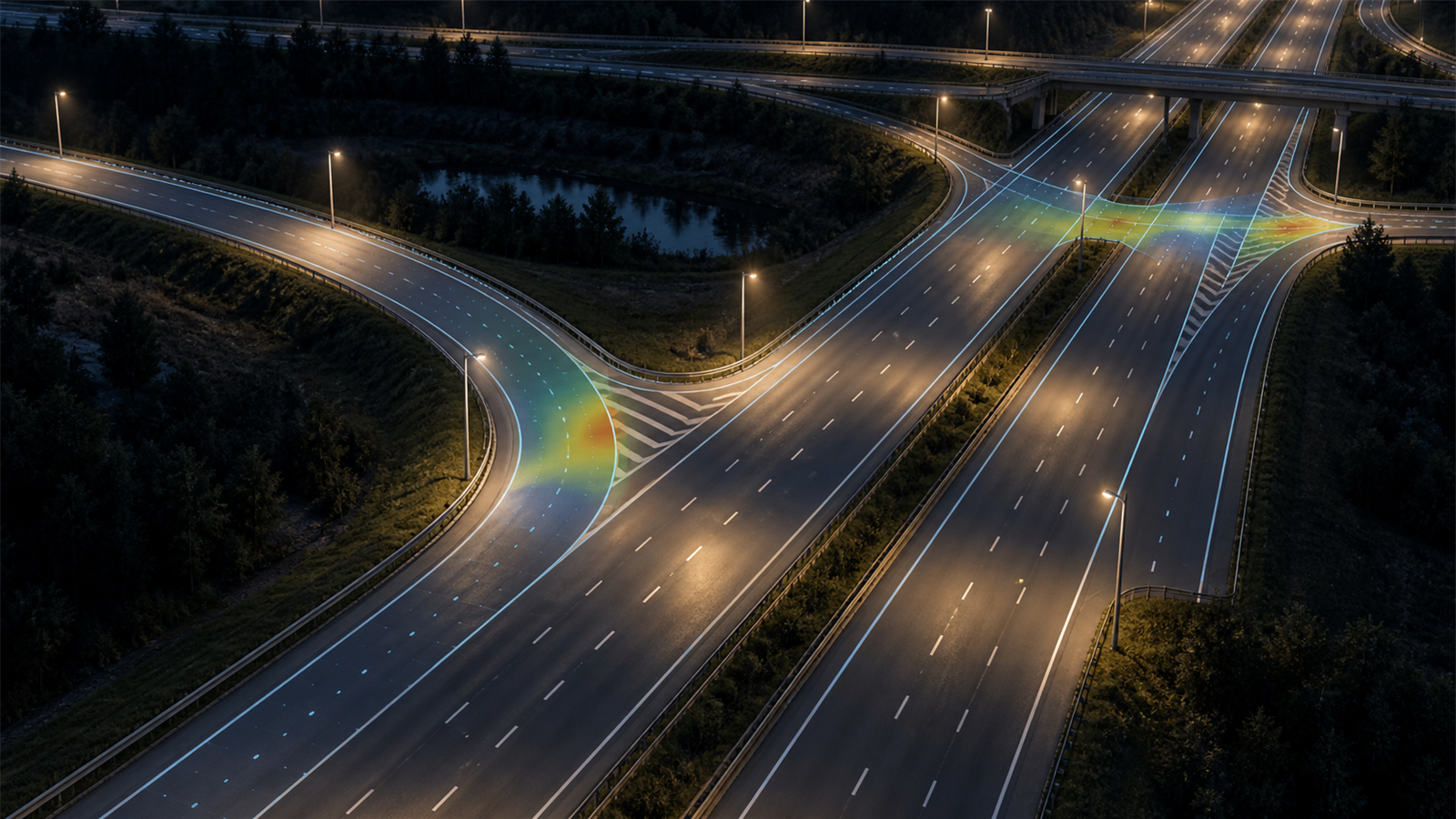
The short answer: divide the model wherever the road task changes
A DIALux highway lighting calculation should not treat a long main carriageway, a curved ramp, a merge taper and a junction as one uniform surface. Divide the model where road width, lane count, driving direction, road surface, lighting class, luminaire arrangement or visual task changes. Evaluate each meaningful segment with the method and criteria agreed for that part of the route.
Use repeatable road-lighting sections for consistent carriageways. Treat ramps, gores, weaving areas, junctions and other conflict zones as separate assessment areas when their geometry or task differs. This prevents a strong average on the straight road from hiding a dark merge, weak uniformity on a curve or glare at an approach.
1. Build a route map before building calculation surfaces
Start from a current scaled alignment or civil drawing. Mark carriageway edges, lane lines, medians, shoulders, verges, barriers, slip roads, acceleration and deceleration lanes, gore areas, junctions, crossings and nearby service roads. Include chainage or another consistent coordinate reference so every segment and pole can be traced back to the design drawing.
Record horizontal curvature, gradients, crossfall, bridge or retaining structures and changes in road level where they can alter visibility or mounting geometry. A flat schematic may be sufficient for an early option study, but it should be labelled as an assumption. Installation or submission work needs geometry accurate enough for the decisions being made.
2. Split the main carriageway when its lighting conditions change
A straight highway section can often be represented by a DIALux street profile with defined lanes, median, emergency lane, footpath or green strip as applicable. DIAL's current street-lighting guidance allows these profile elements and provides separate evaluation fields assigned to a selected lighting class. It also supports common single-sided, opposite, staggered and centre-strip luminaire arrangements.
Create a new calculation segment when the lane count, cross-section, road-surface data, lighting class, pole arrangement, mounting height, tilt, outreach or luminaire changes. Keep enough repeated length for the selected road-lighting method and document the boundaries. Do not average two unlike sections merely because they share a route name.
3. Treat ramps and curved approaches as their own visual tasks
A ramp can change width, radius, gradient, driving direction and sightline within a short distance. Divide long ramps again where the curvature, cross-section or luminaire geometry materially changes. Model merge and diverge tapers deliberately instead of letting their triangular edges disappear outside a rectangular main-road surface.
Check the travel direction through the curve and the driver's likely view of luminaires. A layout that looks regular in plan may create uneven spacing along the travelled path or place a bright source near the line of sight. Where a standard street profile cannot represent the geometry reliably, use an appropriate outdoor model and project-specific calculation objects, then explain the method and its limitations.
4. Assess junctions, gores and weaving areas separately
Junctions and merge zones contain conflicting vehicle paths, lane decisions and changing backgrounds. Draw the actual conflict area rather than extending a straight-lane grid across islands, unused pavement and unrelated shoulders. Confirm whether the governing brief requires an illuminance-based area assessment, a road-luminance method on approaches or both.
Keep approach lanes, the central conflict area and departure lanes identifiable in the results. Add pedestrian crossings, toll points, signs, barriers or other local tasks only when they are within scope and represented with the correct criteria. A single combined average can be misleading when high values beneath one pole compensate numerically for a weak decision point.
5. Assign road surface and observer conditions to the correct segment
Road-luminance results depend on the selected road-surface data and observer geometry. Confirm the actual or specified pavement classification, whether wet-road evaluation is required, the traffic direction and the calculation convention in the governing standard. Do not assume that one default dry surface describes every carriageway, ramp or refurbished section.
For divided roads and two-way layouts, verify which travel directions require separate evaluation. On curves and transitions, confirm that the chosen method still represents the driver's view. If a luminance method is not appropriate for a complex area, document the agreed alternative rather than presenting incompatible results as if they were directly comparable.
6. Keep luminaire data, maintenance and controls consistent
Use the exact manufacturer, model, optic, output and IES or LDT file for every luminaire. Record pole coordinates, mounting height, outreach, orientation and tilt, including changes at medians, ramps and bridges. DIALux can help optimise spacing, mounting height, tilt and distribution for a road profile, but optimisation cannot correct an inaccurate alignment or an unsuitable input file.
Apply an agreed maintenance basis and identify whether results are initial or maintained. If the highway uses dimming, adaptive operation or separate junction circuits, define each operating scene and the conditions it represents. The report should make clear which luminaires are active in every evaluated scenario.
7. Review transitions, glare and surrounding effects
Inspect the boundary between calculation segments, not only the middle of each one. A design can pass two isolated grids yet produce an abrupt visual transition between them. Review minimum values, uniformity, glare and other required road-lighting measures for the correct area, then inspect false-colour plots, isolines and point tables for local patterns that summary values may conceal.
Where the interchange is near homes, habitat, signs, gantries or other receptors, assess spill, upward light and direct intensity using the applicable project method. DIAL's outdoor-lighting guidance includes calculation tools for light-immission quantities and targeted calculation surfaces, but the client, consultant or authority must set the relevant limits and acceptance basis.
Highway calculation decision checklist
Before modelling, confirm: (1) scaled alignment and levels; (2) lane, median, shoulder, ramp and junction geometry; (3) traffic direction and segment boundaries; (4) governing standards and lighting classes; (5) road-surface data and wet or dry conditions; (6) exact luminaire photometry; (7) pole coordinates and mounting geometry; (8) maintenance and control scenes; and (9) required glare, transition and environmental checks.
Before issuing, verify that every change in cross-section or visual task has a justified calculation area, main lanes do not mask ramp or junction results, observer and road-surface settings are traceable, luminaire inputs match the proposed equipment, segment transitions have been reviewed, and assumptions are visible. A DIALux calculation can support evaluation or submission; acceptance rests with the relevant client, consultant or authority.
Authoritative DIALux references used for this guide
DIAL's official Street Lighting with DIALux evo guidance describes custom street profiles with lanes, sidewalks, bike paths, parking, green strips, emergency lanes and medians; selectable standards and lighting classes; multiple luminaire arrangements; optimisation of spacing, height, tilt and distribution; and documentation of evaluation fields, isolux lines and calculation tables.
DIAL's official Outdoor Lighting with DIALux evo guidance describes scaled DWG or image construction, manual luminaire positioning, targeted calculation areas, isolines, false-colour results, lighting scenes and light-immission checks. The correct standard, segmentation and acceptance criteria remain project decisions and should be confirmed before calculation.
Frequently asked questions
Can one calculation surface cover an entire highway interchange?
Usually not usefully. Main carriageways, ramps, merges, junction conflict areas and pedestrian zones can have different geometry, driving directions, criteria and evaluation methods. Separate them where the task changes, then review the transitions between areas.
Should highway ramps be calculated with the DIALux street-lighting tool or as an outdoor area?
Use the street-lighting workflow where a repeatable road profile and its evaluation method represent the ramp accurately. For complex curvature, taper or conflict geometry, an outdoor model with defined calculation objects may be more suitable. Record the chosen method, criteria and limitations.