How should floodlight aiming angles be checked in a DIALux outdoor lighting calculation?
Learn how to test floodlight aiming, beam overlap, glare, dark gaps and boundary spill in a practical DIALux outdoor lighting calculation.
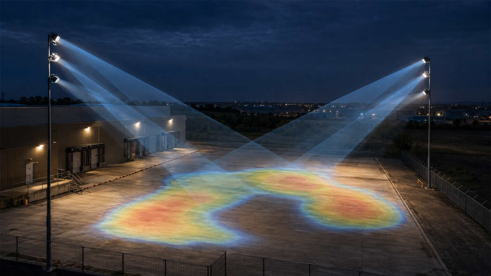
The short answer: aim for the task, then prove the side effects
A floodlight aiming angle should be checked against the actual task zones, mounting geometry, luminaire photometry, obstructions, viewing directions and site boundaries. Do not keep tilting fittings until the average lux reaches a target. A high average can hide dark gaps, hot spots, weak vertical illumination, direct glare or light sent beyond the useful area.
In DIALux, compare deliberate aiming options while keeping the luminaire, output, maintenance factor and calculation surfaces consistent. Review average, minimum and uniformity where relevant, then inspect glare-sensitive viewpoints, vertical surfaces and boundary spill using the criteria agreed for the project.
1. Confirm what the photometric file means before rotating it
Use the exact IES or LDT file for the proposed floodlight, optic and operating setting. A beam name on a catalogue page is not enough: asymmetric distributions, internal tilt, multiple light-emitting surfaces and manufacturer coordinate conventions can make the visible housing direction different from the photometric direction you expect.
Place one fitting in an uncluttered test area and inspect its distribution, orientation and local coordinate system before copying an array. Check that the bright lobe lands on the intended side and that rotation, tilt and mounting direction are recorded consistently. This simple test prevents a correctly calculated but backwards or sideways design.
2. Start from mounting geometry and target zones
Record pole or bracket position, mounting height, setback, outreach and the elevation of the receiving surface. Then divide the site into meaningful zones: vehicle routes, loading faces, work areas, pedestrian edges, gates, storage rows or other tasks. An aiming point should correspond to a real design purpose, not an arbitrary spot chosen because it produces a pleasing render.
Include large canopies, trailers, containers, walls, racks or machinery when they block or reflect a material share of the beam. A clear empty-yard model can make a steep cross-aim look effective even though the installed light path would be obstructed.
3. Compare controlled aiming options, not random adjustments
Create a base arrangement and change one variable at a time: tilt, horizontal rotation, optic, mounting position or output. Recalculate the same calculation surfaces after each change. If both aiming and wattage change together, it becomes difficult to understand why the result improved or which change caused a new problem.
Use isolines, value charts and false-colour views to locate beam edges, overlap and dark pockets, but verify the numerical results as well. A smooth colour plot can still conceal a poor minimum, an isolated hot spot or a boundary exceedance. Keep a short option record so the final report can explain why the chosen aiming pattern was retained.
4. Check more than horizontal illuminance
Horizontal illuminance may be the main criterion for an open yard, but many outdoor tasks depend on vertical or semi-cylindrical information: recognising a person, reading a vehicle face, seeing a loading door or observing equipment. Add calculation surfaces that represent those tasks when the brief requires them instead of assuming the ground result describes everything.
Also review minimum values and uniformity for the correct calculation area. Cropping a surface around the brightest overlap or excluding difficult edges can make the result look stronger without improving the site. Boundaries, obstacle shadows and transition zones should be represented intentionally.
5. Test glare from real approach and working directions
Direct view of a high-intensity floodlight can be uncomfortable or disabling even when the ground illuminance is adequate. Identify likely viewpoints for drivers, pedestrians, operators, security staff and nearby occupants. Check whether a luminaire is aimed toward an approach path or appears close to the line of sight at a critical location.
The applicable glare method depends on the project type and governing criteria. DIALux supports relevant outdoor evaluation workflows, but the software cannot choose the correct observer positions or acceptance limits for an unspecified brief. Record the viewpoints and the source of every target rather than applying a convenient value by habit.
6. Treat light beyond the boundary as a design result
A shallow or outward aim may brighten the far edge while increasing direct intensity toward neighbouring properties, upward light or illumination on sensitive facades. Add the required boundary points or vertical surfaces and calculate the relevant light-immission metrics for the agreed environmental zone and time condition where applicable.
DIAL's official outdoor-lighting guidance lists tools for evaluating luminous intensity, glare-related quantities, upward-light ratios and direct light at window areas. DIALux evo 13.1 also includes selectable obtrusive-light methods and environmental zones. These capabilities support evaluation; the project team must still select the correct current standard, jurisdiction and limits.
Floodlight aiming review checklist
Before calculation, confirm: (1) the exact floodlight and photometric file; (2) local photometric orientation; (3) pole, bracket and mounting geometry; (4) task zones and viewing directions; (5) obstacles and important reflective surfaces; (6) maintenance factor and operating scene; (7) glare and boundary criteria; and (8) the authority, client or consultant responsible for acceptance.
Before issuing the report, verify every copied fitting's tilt and rotation, check average, minimum and uniformity on the correct surfaces, inspect vertical tasks and glare viewpoints, assess relevant boundary spill, and document the final aiming schedule clearly enough for installation. A DIALux calculation can support design evaluation or submission, while acceptance remains with the relevant client, consultant or authority.
Authoritative DIALux references used for this guide
DIAL's official Outdoor Lighting with DIALux evo page explains scaled site construction, manual luminaire positioning, beam-angle and mounting-height adjustment, calculation surfaces, results views, lighting scenes and documentation. Its DIALux evo 13.1 material explains current obtrusive-light calculation objects and environmental-zone selection.
DIAL has also previewed improved floodlight manipulators, mirrored arrangements and aiming points for a future DIALux evo version. Because that article describes planned functionality, this guide does not present those future aiming tools as already available in the current release.
Frequently asked questions
Is there one correct floodlight aiming angle for every outdoor project?
No. The useful angle depends on mounting height, setback, photometric distribution, target geometry, obstructions, viewing directions and boundary criteria. The angle must be tested in the project model rather than copied from a generic rule.
Can I fix low lux simply by tilting a floodlight farther outward?
Sometimes the far edge will increase, but the change can create hot spots, glare, upward light or boundary spill and may weaken nearer zones. Compare a controlled aiming option against all relevant surfaces and viewpoints before accepting it.